- NC Drill files for PCB drilling; 3D model of our PCB; Once the OutJob file is configured, all these files can be uploaded with a few mouse clicks even after changes in the project. Also, the number of OutJob files in the project is unlimited, so in your projects, you can separate them by functionality outputs or by PCB variants.
- Altium 365 Viewer is a simple and convenient way to view and share electronic designs through your browser. Schematics, PCB layout and 3D visualization provides a interactive CAD experience with no downloads or installations required.
Ever since I started using Github and Google Docs, I fell in love with revision control. Instead of keeping multiple copies of essential files and time-stamping every revision, revision tracking information gets stored alongside the file. This environment works great for code, spreadsheets, and documents, and Altium brings these same features into PCB design.
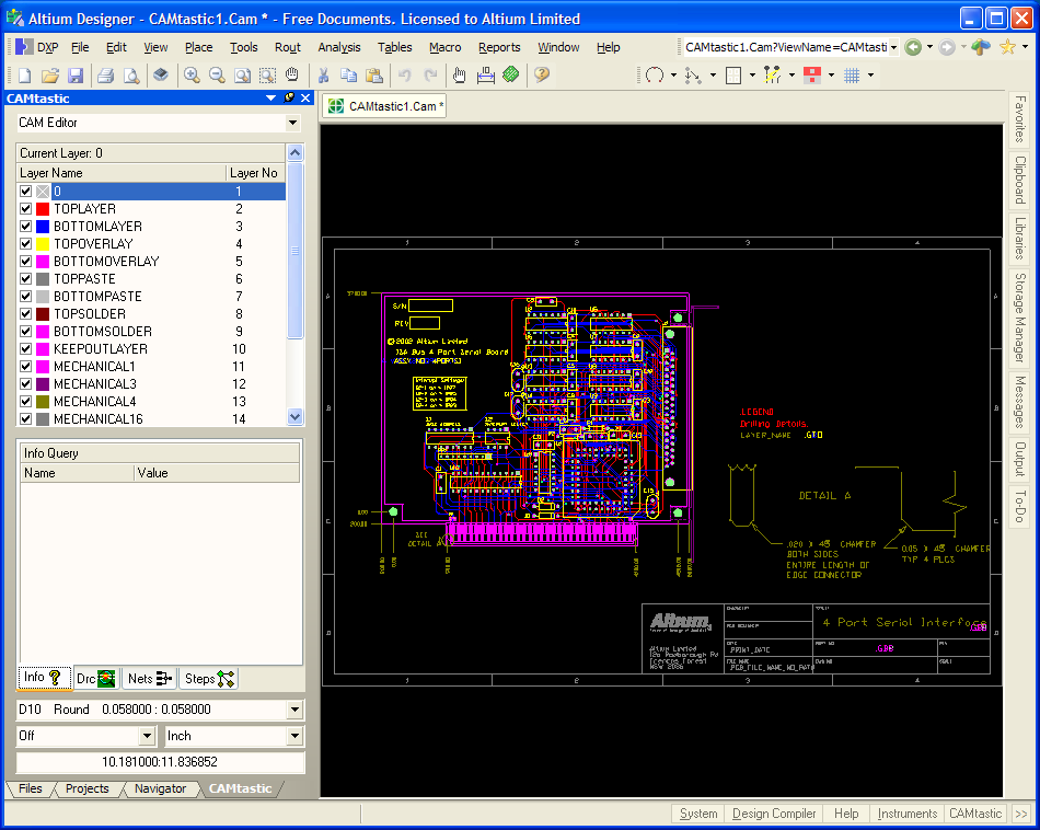
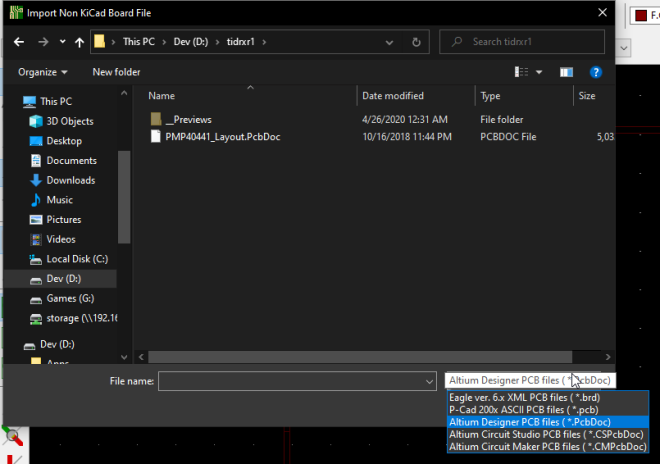
Sep 13, 2017 This article looks at reverse-engineering a PCB layout directly from CAM files loaded into Altium Designer's CAM Editor (CAMtastic®). After importing CAM data into a CAM document, you will notice that the Export to PCB option is grayed-out, regardless of the current CAM Editor mode (CAM or NC). Then import it via: File - Open - Altium EasyEDA offers an excellent experience in importing Alitum Designer’s Schematic and PCB as you can see from the image below of a schematic imported from Altium Designer: If your schematic and PCB are Protel 99se format files, please open at Altium Designer and save as ASCII format, and then import them.

Open Pcb File In Altium Download
Altium 365 enables the same capabilities for revision control. You can easily roll back to earlier revisions of a design, clone a current project, and access a previous revision. You can revert to copies of design files within Altium Designer. If you need to revert to an earlier revision of a local file, you can include this previous revision in your Workspace web instance on Altium 365. If you’ve never used revision control for PCB design, here are some guidelines for local and server-managed revision control in your Altium 365 Workspace.

Where Are My Files Stored?
When you open your Workspace web instance on Altium 365, you won’t see your previous revisions of your schematic files. Everything you see in your Workspace web instance is the most recent revision of your design files. So this begs the question, where can I find earlier revisions of design files?
Whenever you make changes to a schematic, PCB document, or another file, a previous revision will be stored on Altium 365. When you open an Altium Designer project, you can access older revisions of your design files stored on your local machine and online. You can access these different revisions in the Storage Manager panel in Altium Designer.
In the image below, I’ve opened one of my Altium 365 projects in Altium Designer. When I open the Storage Manager panel, I can see local and online revisions of my schematic sheets. I’ve outlined the current revision of this particular schematic file in a red box (see below). This revision is currently open in the background window; it is the current revision of the schematic attached to my project.
To access one of the revisions, simply double click on the earlier revision, and it will open in the Schematic Editor. You can then tile the windows so that you can compare the two revisions side-by-side, as shown in the image below. The earlier revision of the schematic contains three indicator LEDs in the zoomed-in portion of the schematic in the current revision. The current revision only has two indicator LEDs. As you can see in the Comment section of the Storage Manager panel (see above image), one of the LEDs was removed from the schematic.

Once you open up this earlier revision of your schematic, it will appear in the Projects panel’s Free Documents section. You can right-click on this previous revision in the file and click Explore to locate it on your local machine. You can then move this file to another location on your local device. I like to keep the local copies of my project file in the same place as it helps me stay organized.
Comparing revisions
Once you’ve located the earlier revision, you have some options with how to use it. By opening the two schematics side-by-side, I can see exactly where the changes were applied in my schematic file’s newest revision. Note that this allows you to easily see the differences between the current and previous revisions of your schematic. However, there may be other differences that are not obvious; the Compare tool shows a list of differences between the two files.
To access the Compare tool, click on the Projects menu, and click Show Differences. A dialog box will open that allows you to select files to compare. To choose specific files, click on the Advanced Mode option at the bottom of the dialog box. You will see two lists that contain files from the Projects panel. You can now select the files you want to compare. I’ve chosen the earlier revision of my schematic in the left list below, and I’ve chosen the current revision of the schematic on the right list.
After you click OK, you can probe specific differences in each file and inspect these differences visually. The changes will appear as a list of differences, which you can click on to narrow down each file’s specific differences.
Keeping an Earlier revision in Your Current Project
If you’ve decided you want to use the earlier revision of a file in your project, simply rename it and add it to your current project by dragging it into the Projects panel. You can then commit and push your project to your Workspace web instance using the revision control tools in the Projects panel. You can also remove the older revision of the file from your project as you would any other file.
In the image below, I’ve added my previous project revision, and now I’m about to push the project back to my Altium 365 Workspace. After you add the previous revision into the project and remove the unneeded files, simply right-click on the project file and select Commit Whole Project under the revision Control entry. You’ll see the Commit to revision Control dialog appear, and you can select specific files in your project to push to your Altium 365 Workspace.
Once I click Commit and Push, the earlier revision of my schematic will be added into revision control. It will now appear in its revision chain. You can implement the same revision control tracking features shown above for PcbDoc files and other files in your project. Note that, in the above window, I’ve removed the additional schematic file from my project, but I could have kept this other file in my project. It would continue to have its own revision chain tracked in my Altium 365 Workspace and accessible in the Storage Manager panel.
Anyone with access to the project will also be able to access these earlier file revisions. Be sure to communicate with your team and keep track of user access within your Altium 365 Workspace. For a more in-depth look at regulating access to different projects in your Altium 365 Workspace, take a look at this tutorial on controlling user access.
Hopefully, this short tutorial helps you access earlier revisions of files stored on your Altium 365 Workspace. This is a simple way to track your files' previous revisions without manually tracking a long list of files on your local computer. Note that Altium Designer will keep track of your earlier file revisions on your local machine as you edit them. These are also accessible from the Storage Manager panel in the Local History list (see the above window). For more information about revision control on Altium 365, see this tech doc.
Altium 365 is bringing an unprecedented amount of integration to the electronics industry. Until now version control was relegated to the world of software development, now designers can work from home and reach unprecedented levels of efficiency.
We have only scratched the surface of what is possible to do with Altium 365. You can check the product page for a more in-depth feature description or one of the On-Demand Webinars.
.pcb File
 Files for Manufacture
 Our project is now complete. The schematic is drawn, the list of components is complete and verified, the PCB is composed and has been checked for errors, and the assembly drawing is ready. The next step is to upload all the required files in order for the PCB manufacturer and assembler to get the final (and already working) device. At the very least, the manufacturer should get information about the PCB materials and layers set, NCDrill files, and Gerber or OBD++ files to create a conductive pattern on the layers of the designed PCB. These files can be uploaded individually, but it is much easier and faster to use the OutJob file to output all the necessary files at once. Each output is configured with its own settings output format. OutJobs are very flexible – they can include as many or as few outputs as required and any number of OutJobs can be included in a project. The best approach is to use one OutJob to configure all outputs required for each specific type of output being generated from the project. Let’s create the OutJob file for exporting all output files of our drone PCB.
Make sure that project Kame_FMU.PrjPCB is active. Select File > New > Output Job File from the main menus to create a new OutJob file related to the project. A new OutJob editor will open in the design space with the settings of output files. In this editor, you can specify all the necessary documents for export and upload them at the same time. Simultaneously, the new.OutJob document will appear in the project tree.
The main section of this editor is Outputs and it is divided into groups depending on the type of documentation: Assembly, Fabrication, Report, etc. To manufacture and assemble the drone PCB, we need to get the following set of files:
- Schematic Drawing
- Assembly Drawing
- Pick and Place file for automatic component placement
- Bill of Materials report
- Board Stackup Information
- Gerber/ODB++ files to replicate the conductive copper pattern on a real PCB
- NC Drill files for PCB drilling
- 3D model of our PCB
Once the OutJob file is configured, all these files can be uploaded with a few mouse clicks even after changes in the project. Also, the number of OutJob files in the project is unlimited, so in your projects, you can separate them by functionality outputs or by PCB variants. In the following guides, all the necessary documents and files will be configured and generated depending on their type
Comments are closed.